Solar-powered light barrier across the driveway
Published
by Thorsten von Eicken
At https://blog.voneicken.com/2018/light-barrier/
In
Driveway Entrance Chime Powered by Solar Light Barrier
Tagged
Light Barrier
,
Stm32
,
Rfm69
,
Solar
Light barrier using pulsed IR. The transmitter is based on NE555 timers and the receiver on a special-purpose IR receiver, an stm32 for control, and an rfm69 radio to transmit interruptions.
See driveway entrance chime powered by solar light barrier for the project intro.
IR receiver
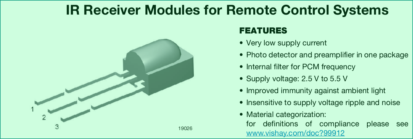
At the core of the project lie very efficient IR LEDs to transmit light to a special-purpose receiver that is tuned to a specific frequency and expects to receive a train of light pulses. The specific receiver I use is a Vishay TSOP38338, which is a 3-pin device that outputs low when it receives incoming IR light pulses and high when it doesn’t.
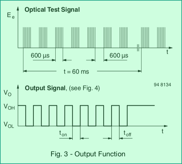
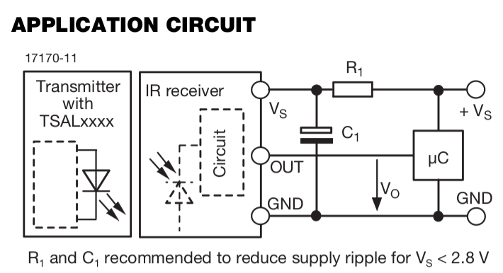
The light pulse train it expects to receive must have a frequency of 38kHz and last for at least 6 and at most 35 pulses. Something like shown in the diagram on the right. A typical circuit is shown below, the only thing noteworthy really is the suggested power supply filtering capacitor, other than that all that’s needed is to connect the detector output to a gpio input on the microcontroller.
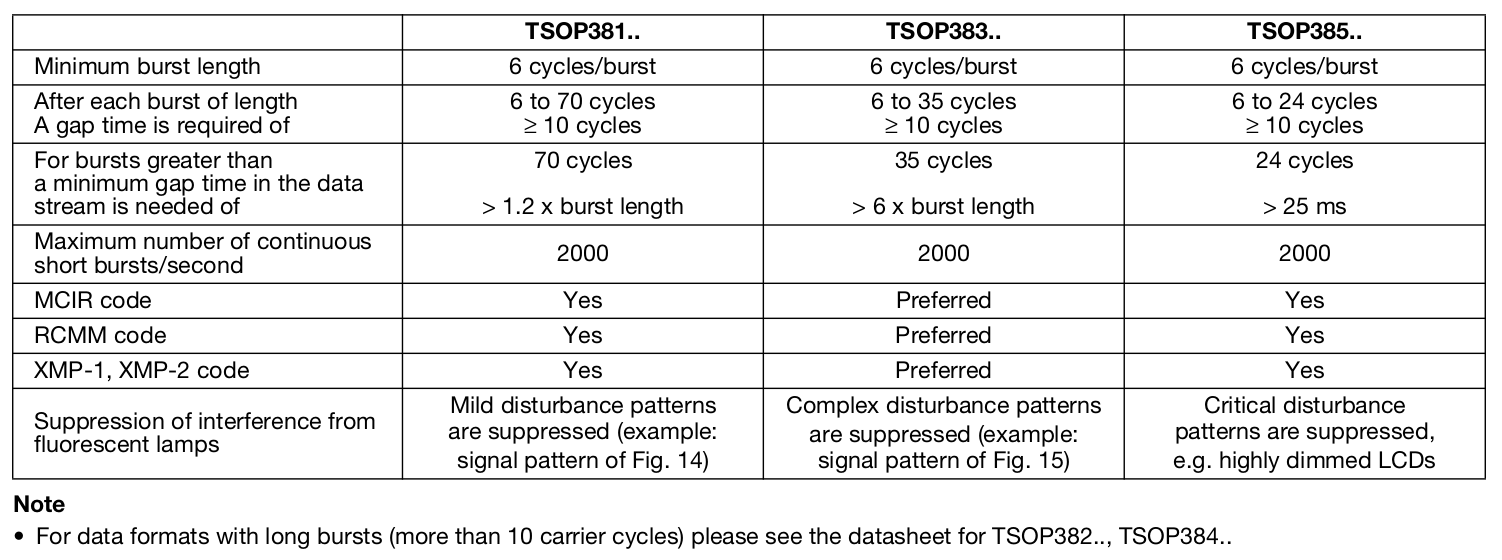
There are other versions of the receiver that respond to slightly different frequencies and burst lenths as summarized in the table below.
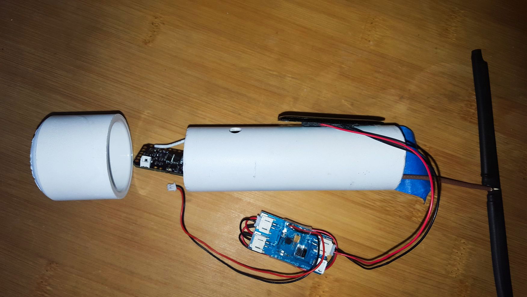
The photo at the right shows the semi-assembled unit with the solar charger at the bottom, the JeeNode Zero half sticking out of the PVC pipe, the solar panel at the top, and a dipole antenna sticking out at the bottom of the PVC pipe.
IR transmitter
The IR transmitter needs to generate the required light pulses at the right frequency and with an appropriate duty cycle. I chose to emit around a dozen light pulses at a frequency of about 10Hz. This way even someone walking rapidly through the light barrier blocks the light for a couple of pulse trains, which is something the receiver should be able to detect reliably. Hopefully an insect flying through the light barrier only causes at most one pulse train to be blocked so it doesn’t cause false positives.
The IR light is emitted by powerful LEDs. I chose Vishay TSAL6100 LEDs, which emit about 170mW/sr of light at 100mA consumption with a beam angle of 20 degrees. Osram has some alternative LEDs which are perhaps even better, specifically the SFH 4544. All of these emit quite powerful light focused relatively narrowly but not as narrow as a laser beam!
I haven’t used NE555 timers in over a decade but had a couple laying around so I thought I’d refresh my skills and a NE556 instead of reaching to a microcontroller just to implement two timers. That sounded fun and smart at the time, but in hindsight I would not do that again and may actually replace the whole thing, but more on that later.
The circuit is really simple:
- a 555 oscillator running at 10Hz to turn the light pulses on/off, the duty cycle is very skewed so it turns on just long enough for about a dozen pulses to be emitted (the exact count is voltage and temperature dependent).
- another 555 oscillator that is gated by the first one and that runs at 38kHz in order to pulse the LEDs at the right frequency.
- a constant current drive that drives the LEDs (I use two LEDs in series) at approx 100mA.
- a voltage divider to reset the first 555 oscillator when the voltage drops way down in order to save the battery.
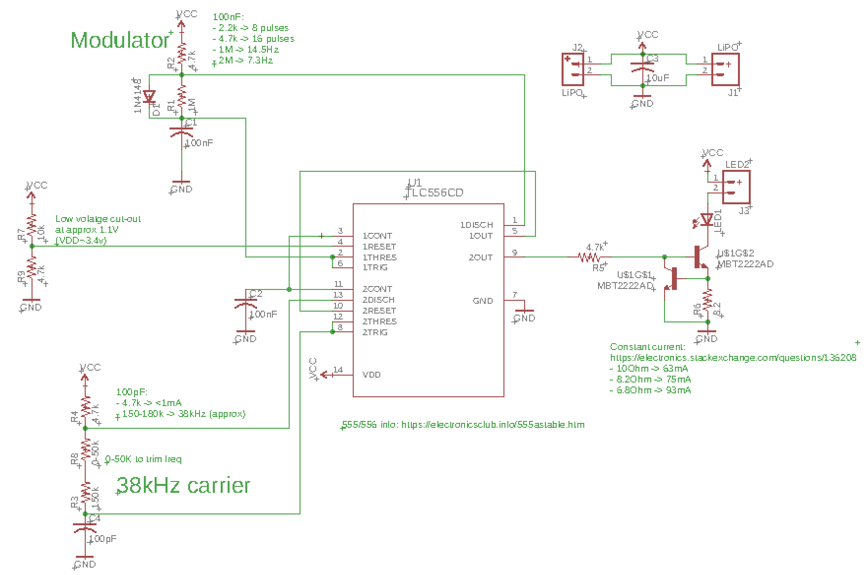
I first prototyped the circuit and it all went well until I measured the current: whoa! Of course when the LED is active that draws 100mA but when the LED was off the circuit was also consuming several mA, which is not practical on battery. I realized that the culprits were the resistor voltage dividers that set the oscillator frequencies! In order to fix the problem I changed them out for the largest values that I had on-hand. This brought the LED-off power consumption down to 100µA, which is nothing to rave about but at least tolerable.
Overall, using the NE556 has been rather disappointing and I wouldn’t do it again. Here is the list of disappointments:
- The power consumption is at least 10x higher than if I had used an STM32L0 microcontroller.
- The low-voltage cut-off to protect the battery is crude and not really sufficient.
- The tuning of the frequency/duty cycle is less precise and less easy to change than with a µC.
- The number of parts is larger than with a µC (although cheaper).
- There is no monitoring of the battery voltage possible.
Solar
This is the first project I am trying to power via solar (oops). The reason is that the IR LEDs on one end and the IR detector on the other end use an order of magnitude more power than my other battery operated gizmos and that means that I’d either have to use a quite large battery or change batteries weekly. So I’m looking for a small amount of solar power, which is not entirely trivial due to the plant coverage around the driveway entrance.
The first step is to do some power consumption calculations. The IR receiver is easy: the IR detector’s consumption dwarfs everything else on the board as it consumes a steady 450µA. On a 1000mAh battery that translates to about 90 days of run-time. I’m using a 240mAh battery and thus can expect about 2-3 weeks.
The power consumption of the IR transmitter needs to model the duty cycle of the LEDs:
| LED [mA] | freq [Hz] | pulses | period [ms] | avg [mA] |
|---|---|---|---|---|
| 110 | 38000 | 16 | 100 | 0.23 |
LED on-time for one pulse train is 16*(1/38000)/2 = 2.1ms which over 100ms results in an average
of 230µA power draw.
To implement the solar charging I decided to start simple and use low-cost LiPo charger modules that support solar. The modules are based on a chinese charger chip, the CN3065, available from the typical low cost sources as “Mini Solar Lipo Charger Board CN3065”.
The chip really is a USB-powered LiPo charger, except that it handles low-voltage conditions gracefully by degrading into a sort of PWM mode. This means that when a 6V solar panel provides ample power it charges the battery as if it were on USB. When the solar power becomes marginal it turn the charging on, which lowers the panel voltage such that the low-coltage cut-out disconnects the panel, which then goes up in voltage again and the cycle repeats. It’s not the greatest set-up but worth seeing whether this does it.
The solar panels I’m using are tiny 6V 16mA panels. In theory, if they get a few hours of sun per day they should be sufficient. The key question is in the mounting and resulting exposure.
Code
The sketch running on the IR detector is relatively simple. The IR detector input pin is connected to an interrupt routine which sets a “last seen” timestamp whenever the detector indicates that light pulses are received. The main loop runs every 300ms and checks whether the timestamp is more than 300ms old. If it is it sends an MQTT message to indicate that the light barrier has be interrupted.
The sketch also transmits the battery voltage every few minutes so I can track the charging vs. consumption.
Mounting
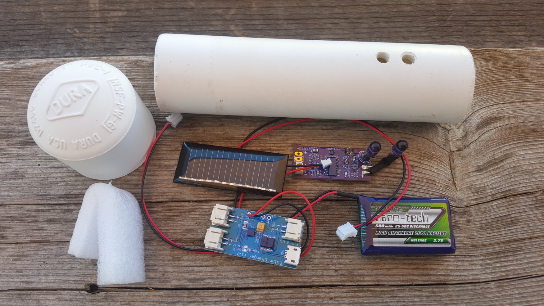
To keep everything simple I used PVC pipe left-overs to house the electronics. I drilled holes for the LEDs and IR detector and used PVC caps at the top, leaving the bottoms open for now. I’ll have to seal them with some tape or foam so spiders don’t set-up shop inside.
Status
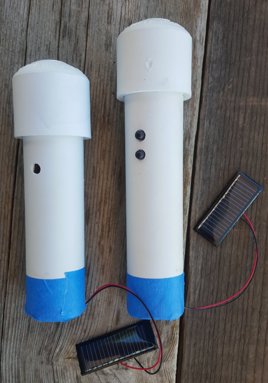
The light-barrier part is working very well. I am not getting spurious alerts and everything seems quite reliable.
The solar on the IR transmitter also appears to function OK, I wish I had remote monitoring capability. The solar on the IR detector is not working so well, it just doesn’t get much sun due to being under trees. Maybe a larger panel could do or maybe I can tweak the location a bit. It’s too early to tell.
The RF transmission of the interruptions is not working well, unfortunately. THere is just too much green stuff between the unit and my current RF-MQTT gateway. I tried using a better antenna and that improved things, but not enough. I am planning to add more gateways so this project will be a bit on hold until that happens.
To be continued…