ESP8266 Deep-Sleep with Periodic Wake-up
Published
by Thorsten von Eicken
At https://blog.voneicken.com/2018/lp-wifi-esp8266-1/
In
Running Wifi Microcontrollers on Battery
Tagged
Low-Power
,
Wifi
,
Esp8266
The esp8266 can last for years on battery in deep-sleep mode, so that’s a good place to start. The question really is how often can it wake-up?
The best way to find out is to run some experiments! The experiments will have the esp8266 wake-up from deep-sleep (basically a reset), send some data to a server on the local network using raw TCP, and go back to sleep. Really basic.
Diving one level deeper, the esp8266 will need to go through the following phases during its waking time:
- initialize the microcontroller (set-up clocks, flash access, caches, etc)
- scan wifi channels to locate the Wifi access point
- exchange multiple packets to associate with the access point, including crypto operations when dealing with secure access points
- request-response to DHCP server to obtain an IP address
- ARP broadcast and response to obtain the server’s MAC address
- TCP connection set-up, data transfer, and tear-down
- disconnect from the access point
I tried to derive the time the above steps might take from first principles, e.g. the network protocols, and I almost fell from my chair when I saw the first packet traces! I was off by an order of magnitude! So I’ll spare you that derivation…
Experimental set-up

The set-up I use is as follows:
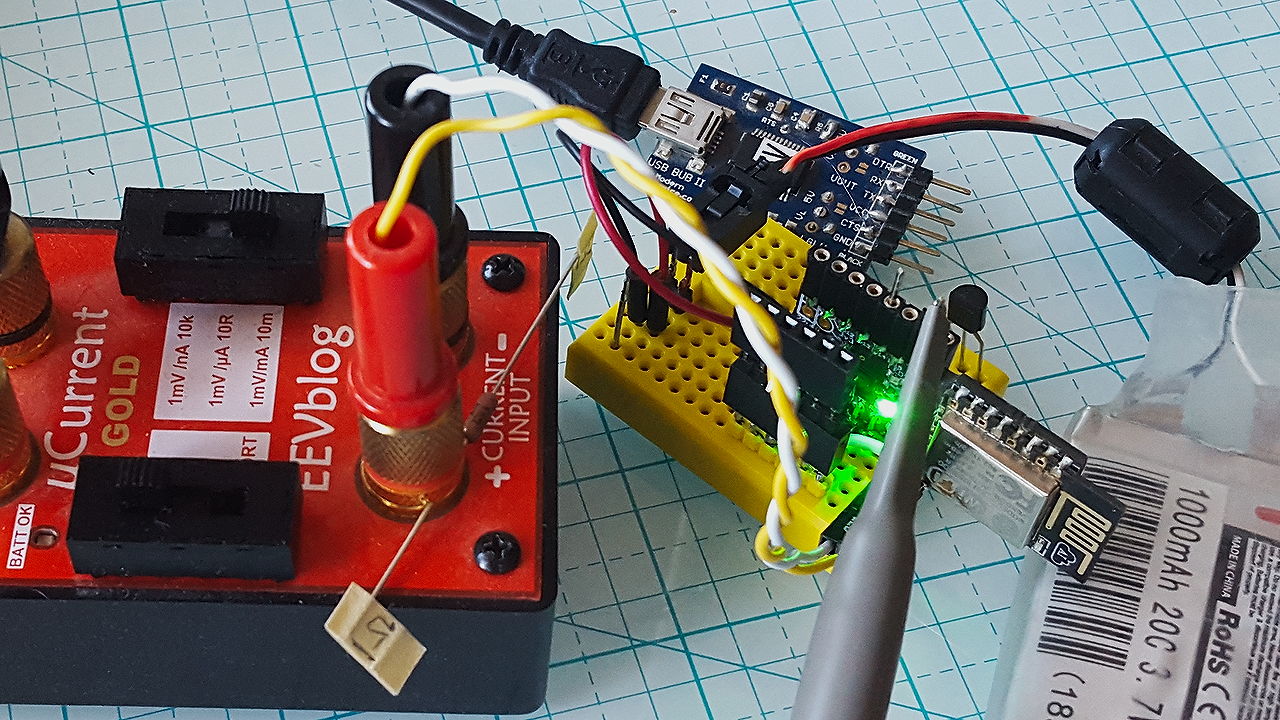
- a small custom PCB that houses an esp-12e module with a switching power regulator and an FTDI-style connector to access the serial port and programming pins
- a jumper on the ground connection leading into the esp8266 module to measure supply current
- a uCurrent Gold to amplify the current (a 1 Ohm resistor would have probably done just fine given the magnitude of the currents)
- a LiPo battery to power the esp8266 without interfering with oscilloscope ground
- a FTDI USB-serial adapter to program the esp8266
- an oscilloscope to measure the current and a probe on a random esp8266 gpio pin to trigger the scope
In addition, I set-up a controlled Wifi environment:
- an open unencrypted access point using a USB-adapter attached to a ODROID SBC
- hostapd running on the ODROID with bridging to my home network where my DHCP server runs
- a second USB-Wifi adapter attached to my desktop box running in monitor mode to capture the Wifi packets as they go through the air
- a simple TCP service cobbled together using netcat running on my desktop to accept the esp8266’s TCP connections a log the data sent into a file
And for comparison purposes I also used a secured/encrypted home Wifi network with a Senao access point and an Android cell phone in hot-spot mode.
As I dove in I found two issues with my set-up, which I want to mention up-front. The first is that the Wifi adapter in monitor mode misses some packets, specially some back-to-back packet combinations are systematically missed and I didn’t find any tricks to fix that.
The second issue is that there seems to be a high packet loss between the esp8266 and the access point on the ODROID, which I cannot explain. It happens whether the two systems are 1ft/30cm or 10ft/3m apart. I tried changing preamble sizes, etc, to no avail. I compared with using my home Wifi and realized it’s not all that different plus, as we’ll see, the number of retransmissions don’t actually affect the overall outcome.
First measurements
The esp8266 runs a simple sketch in the Arduino framework. The sketch starts by loading data from the real-time clock memory, which doesn’t get lost during deep-sleep. Then it initializes the Wifi in one of 4 modes based on the config data, connects to a TCP server on the network using the server’s IP address (no DNS lookup), and sends a line of text with some timing info to the server. Finally it goes back to deep-sleep.
The 4 modes differ in the amount of information passed into the Wifi initialization functions
WiFi.begin and WiFi.config:
| mode | ssid, passwd | channel, bssid | ip, mask, gw, dns |
|---|---|---|---|
| 0 | ✔ | ||
| 1 | ✔ | ✔ | |
| 2 | ✔ | ✔ | |
| 3 | ✔ | ✔ | ✔ |
A quick look at the information coming out of the sketch shows the following:
Mode 0, Init 34 ms, Connect 2927 ms, Total 2961 ms, SSID test, SDK 3.0.0-dev(c0f7b44)
Mode 1, Init 34 ms, Connect  177 ms, Total  211 ms, SSID test, SDK 3.0.0-dev(c0f7b44)
Mode 2, Init 34 ms, Connect 2877 ms, Total 2911 ms, SSID test, SDK 3.0.0-dev(c0f7b44)
Mode 3, Init 34 ms, Connect  137 ms, Total  171 ms, SSID test, SDK 3.0.0-dev(c0f7b44)
These are representative messages for many iterations. The init time is from the start of the
microcontroller clock to the beginning of the sketch’s setup() function, the connect time is from
the start of setup() to the moment the wifi subsystem reports that it is connected to the access
point, and the total time is from the start of the clock to calling the function to go into
deep-sleep.
It is immediately obvious that there is over an order of magnitude difference in those 4 modes, i.e. from about 140ms to connect to Wifi to almost 3 seconds! We could start hypothesizing based on the differences in the four modes, but it’s far more interesting to just focus on mode 0 and to see what all goes on.
Mode 0: basic WiFi.begin()
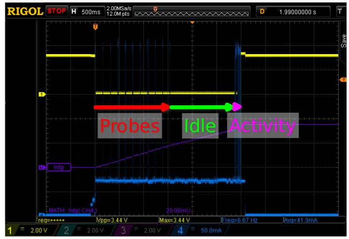
Diving right in, this is a scope capture of a full wake-up cycle:

WiFi.begin(ssid,passwd) on an open access
point.
The yellow trace is a gpio output that goes low at the start of the Arduino setup() function and
rises again just before loop() completes and puts the microcontroller back into deep sleep.
Each horizontal division corresponds to 500ms, thus the sketch runs for a tad under 3 seconds,
i.e. just about the time claimed by the sketch.
The blue trace shows power consumption at the tune of 50mA per vertical division. It starts with a couple of stair steps as the uC initializes and mostly sits at about 140-150mA. The high peaks up to 350mA correspond to Wifi transmissions.
In a first phase, shown as “Probes” in the scope capture,
the esp8266 sends probe requests on all channels in order to locate the access point.
These packets are shown in the packet dump below where packets sent by the esp8266 are marked with a ->
and packets sent by the AP with a <-.
The first column is a packet counter (the skipped packets are beacons) and the second column
shows the time elapsed with millisecond resolution since the start of the capture.
Note that the ACK packets are Wifi-level acks of the probe responses and due to the
limitations mentioned earlier it is likely that additional ACKs were missed.
   51 66.208s -> Probe Request (test) [5.5* 11.0* 1.0* 2.0* 6.0 12.0 24.0 48.0 Mbit]
   57 66.519s <- Probe Response (test) [1.0* 2.0* 5.5* 11.0* 6.0 9.0 12.0 18.0 Mbit] CH: 6
   60 66.666s -> Probe Request (test) [5.5* 11.0* 1.0* 2.0* 6.0 12.0 24.0 48.0 Mbit]
   61 66.671s <- Probe Response (test) [1.0* 2.0* 5.5* 11.0* 6.0 9.0 12.0 18.0 Mbit] CH: 6
   62 66.673s -> Acknowledgment RA:74:da:38:06:52:32
   67 66.819s -> Probe Request (test) [5.5* 11.0* 1.0* 2.0* 6.0 12.0 24.0 48.0 Mbit]
   68 66.824s <- Probe Response (test) [1.0* 2.0* 5.5* 11.0* 6.0 9.0 12.0 18.0 Mbit] CH: 6
   69 66.826s -> Acknowledgment RA:74:da:38:06:52:32
   72 66.973s -> Probe Request (test) [5.5* 11.0* 1.0* 2.0* 6.0 12.0 24.0 48.0 Mbit]
   73 66.978s <- Probe Response (test) [1.0* 2.0* 5.5* 11.0* 6.0 9.0 12.0 18.0 Mbit] CH: 6
   74 66.979s -> Acknowledgment RA:74:da:38:06:52:32
   79 67.131s <- Probe Response (test) [1.0* 2.0* 5.5* 11.0* 6.0 9.0 12.0 18.0 Mbit] CH: 6
   80 67.133s <- Probe Response (test) [1.0* 2.0* 5.5* 11.0* 6.0 9.0 12.0 18.0 Mbit] CH: 6
   81 67.134s <- Probe Response (test) [1.0* 2.0* 5.5* 11.0* 6.0 9.0 12.0 18.0 Mbit] CH: 6
   82 67.136s <- Probe Response (test) [1.0* 2.0* 5.5* 11.0* 6.0 9.0 12.0 18.0 Mbit] CH: 6
   83 67.138s <- Probe Response (test) [1.0* 2.0* 5.5* 11.0* 6.0 9.0 12.0 18.0 Mbit] CH: 6
   84 67.139s <- Probe Response (test) [1.0* 2.0* 5.5* 11.0* 6.0 9.0 12.0 18.0 Mbit] CH: 6
After the probes complete, there is a 1.5-2 second radio pause (“Idle” in the capture). Presumably during this time the esp8266 waits for other APs on other channels to potentially respond so it can pick the one with the best signal. In this case there is only one AP so it eventually proceeds on the channel being monitored. The rest of the activity (“Activity” in the capture) is concentrated in a rather short time period at the end of the whole cycle.
Mode 0 activity
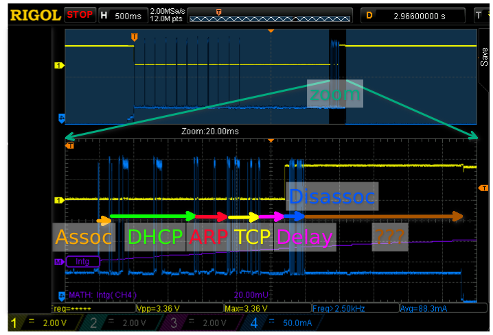
To view the activity at the end of the wake period here is a zoom-in of the same capture with a horizontal resolution of 20ms per division.

Let’s go through all the phases marked-up in the scope capture using the packet captures to understand exactly what is happening.
In the first phase of the activity the esp8266 authenticates and associates with the AP (there’s no password but an auth exchange still happens). The very first packets seen on the air actually deassociate to ensure that there is no old association state left in the AP:
  121 68.918s -> DeAuthentication (5c:cf:7f:05:c0:db): Deauthenticated because sending station is leaving (or has left) IBSS or ESS
  122 68.918s -> DeAuthentication (5c:cf:7f:05:c0:db): Deauthenticated because sending station is leaving (or has left) IBSS or ESS
  123 68.918s <- Acknowledgment RA:5c:cf:7f:05:c0:db
  124 68.918s -> Authentication (Open System)-1: Successful
  125 68.918s <- Acknowledgment RA:5c:cf:7f:05:c0:db
  126 68.924s <- Authentication (Open System)-2:
  127 68.924s -> Acknowledgment RA:74:da:38:06:52:32
  128 68.926s -> Assoc Request (test) [5.5* 11.0* 1.0* 2.0* 6.0 12.0 24.0 48.0 Mbit]
  129 68.926s <- Acknowledgment RA:5c:cf:7f:05:c0:db
  130 68.929s <- Assoc Response AID(1) :: Successful
  131 68.930s -> Acknowledgment RA:74:da:38:06:52:32
Now that the esp8266 is associated it can ask for an IP address using DHCP:
  133 68.932s -> IP 0.0.0.0.68 > 255.255.255.255.67: BOOTP/DHCP, Request from 5c:cf:7f:05:c0:db, length 308
  134 68.936s <- Acknowledgment RA:5c:cf:7f:05:c0:db
  135 68.944s -> IP 0.0.0.0.68 > 255.255.255.255.67: BOOTP/DHCP, Request from 5c:cf:7f:05:c0:db, length 308
  136 68.947s <- IP 192.168.0.1.67 > 192.168.0.106.68: BOOTP/DHCP, Reply, length 300
  137 68.950s -> Acknowledgment RA:74:da:38:06:52:32
  138 68.952s -> IP 0.0.0.0.68 > 255.255.255.255.67: BOOTP/DHCP, Request from 5c:cf:7f:05:c0:db, length 308
  139 68.955s <- Acknowledgment RA:5c:cf:7f:05:c0:db
  140 68.961s -> IP 0.0.0.0.68 > 255.255.255.255.67: BOOTP/DHCP, Request from 5c:cf:7f:05:c0:db, length 308
  142 68.971s <- IP 192.168.0.1.67 > 192.168.0.106.68: BOOTP/DHCP, Reply, length 300
  143 68.974s -> Acknowledgment RA:74:da:38:06:52:32
At this point the esp8266 has its IP address, it now sends gratuitous ARPs in order to ensure that no-one else is using the same IP address. Shortly thereafter it requests the MAC address of the server to which data is to be sent. This is repeated because for some reason the server didn’t respond.
  144 68.975s -> ARP, Request who-has 192.168.0.106 tell 192.168.0.106, length 28
  145 68.976s <- Acknowledgment RA:5c:cf:7f:05:c0:db
  146 68.982s -> ARP, Request who-has 192.168.0.106 tell 192.168.0.106, length 28
  147 68.986s -> ARP, Request who-has 192.168.0.2 tell 192.168.0.106, length 28
  148 68.986s <- Acknowledgment RA:5c:cf:7f:05:c0:db
  149 68.992s -> ARP, Request who-has 192.168.0.2 tell 192.168.0.106, length 28
  150 68.992s <- ARP, Reply 192.168.0.2 is-at b8:97:5a:90:54:5a, length 46
  151 68.993s -> Acknowledgment RA:74:da:38:06:52:32
Finally everything is ready for some data! This is the TCP connection:
  152 68.994s -> IP 192.168.0.106.49669 > 192.168.0.2.12345: Flags [S], seq 6509, win 2144, options [mss 536,nop,nop,sackOK], length 0
  153 68.995s <- Acknowledgment RA:5c:cf:7f:05:c0:db
  [SYN-ACK packet missing from capture]
  154 68.996s -> Acknowledgment RA:74:da:38:06:52:32
  155 68.998s -> IP 192.168.0.106.49669 > 192.168.0.2.12345: Flags [.], ack 2924126972, win 2144, length 0
  156 68.998s <- Acknowledgment RA:5c:cf:7f:05:c0:db
  157 68.999s -> IP 192.168.0.106.49669 > 192.168.0.2.12345: Flags [P.], seq 0:86, ack 1, win 2144, length 86
  158 69.001s <- Acknowledgment RA:5c:cf:7f:05:c0:db
  [TCP ack packet missing from capture]
  159 69.005s -> Acknowledgment RA:74:da:38:06:52:32
  160 69.007s -> IP 192.168.0.106.49669 > 192.168.0.2.12345: Flags [F.], seq 86, ack 1, win 2144, length 0
  161 69.008s <- Acknowledgment RA:5c:cf:7f:05:c0:db
  [FIN+ACK packet missing from capture]
  162 69.010s -> Acknowledgment RA:74:da:38:06:52:32
  163 69.011s -> IP 192.168.0.106.49669 > 192.168.0.2.12345: Flags [.], ack 2, win 2143, length 0
  164 69.012s <- Acknowledgment RA:5c:cf:7f:05:c0:db
And it’s done! The code has a delay() for 20ms that I forgot to remove before it puts the esp8266 to sleep.
A few of these are overlapped by the shutting down of TCP and
then the esp8266 disassociates from the AP. There are a total of 11 disassociation frames (not
all are shown here):
  165 69.029s -> Disassociation: Disassociated because sending station is leaving (or has left) BSS
  166 69.029s <- Acknowledgment RA:5c:cf:7f:05:c0:db
  167 69.030s -> Disassociation: Disassociated because sending station is leaving (or has left) BSS
  168 69.030s <- Acknowledgment RA:5c:cf:7f:05:c0:db
  169 69.030s -> Disassociation: Disassociated because sending station is leaving (or has left) BSS
  170 69.030s <- Acknowledgment RA:5c:cf:7f:05:c0:db
  171 69.030s -> Disassociation: Disassociated because sending station is leaving (or has left) BSS
  172 69.031s <- Acknowledgment RA:5c:cf:7f:05:c0:db
After the last packet it takes another 90ms before the esp8266 actually powers down, what it does during that period is not entirely clear.
What have we learned?
The most obvious observation from this trace is that the probing takes the bulk of the time! This can be seen not only from the scope capture but also from the fact that the two modes that specify the channel and bssid (modes 1 and 3) are much faster in connecting than the other two. It’s clearly worthwhile to eliminate the probing from the wake-up, which is done in the code by using the RTC RAM to remember the channel and bssid info from previous iterations.
The DHCP and ARP phases also take up quite some time of the activity period. We should be able to eliminate the DHCP phase by using a static IP or remembering the dynamic one but the ARP phase is likely to stay.
More about these optimizations in the next post